|
|
|

|

|
March 2004
|
|


|
PROJECT MAY
Sponsored by

®
|
|
|
|
|
|
March 2 -
TimG
Finally warm enough for glue to dry so
fabrication can begin on the test enclosures. The
first 2 cabinets are ready to go. These drivers require 3/4" recess for
flush mounting so I had to laminate up 1.5" baffles. I will need to add weatherstrip to flush mount the 2234H's in these cabinets because the
older 15" drivers only require 5/8" recess for flush mounting. First set
of measurements will be done with 1500AL, and 2426H on a 16" x 6"
biradial horn.
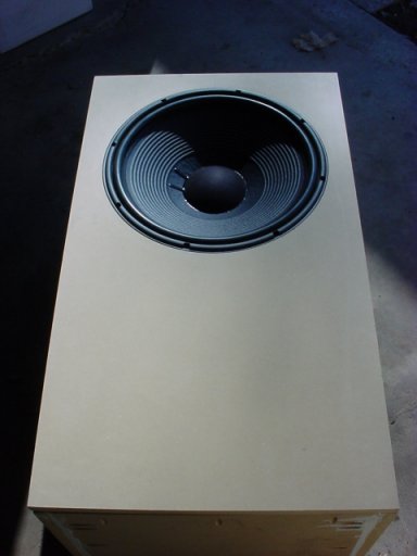
The test enclosure dimensions are: OD 15.75"
x 18.5" x 32.5" ID 14.25" x 17" x 31" - (4) 31" x 1.5" x 3.5" vertical
braces so 3.97 cu ft - driver volume no stuffing at this time Weather
permitting, and with the help of a fellow speaker builder, I will start
on 4 more stackable bass modules on Sunday. I am now thinking that I
will try to target 5 cu ft boxes and reduce the volume if we need to
rather than building even more boxes. .
|
|
|
|
March 3 -
TimG
Budget horn proposal:
I'm thinking that some people may want to
build a DIY project similar to the Project May, but will not be able to
afford the original drivers or custom CNC machined wood horns (me for
instance). As I build cabinets and measure the flagship drivers I will
also be measuring other alternative drivers in the cabinets so that I
will be able to propose an alternative design that will be more
affordable to build.
My plan is to use drivers and horns that are
similar enough that someone could start with affordable vintage drivers
and then eventually upgrade to the full S9800 driver complement, or at
least the less expensive diaphragm versions (2430, 045ti). I don't have
access to a 1500FE, but that could be considered for an alternative
woofer as well.
I will be measuring a 2226H and 2234H as
alternative woofers. For midranges I will be measuring the 2426H on 2
horns that I have on hand. I will also be measuring a BMS 4590P, JBL
2450, and 2446, that a forum member will be sending me, on a 2380A horn.
I found another 1" throat horn and
supertweeter that I would like to try, but I can't figure out how to get
the faceplate off the supertweeter that I have. Here is the plan:
I want to get this dirt cheap
piezo driver
tear the horn off and then mount the driver from this
combo
behind the horn.
I already have one of the FT17H drivers.
Here is a
mid horn
that appears very similar to the S9800 horn and we could
add a JBL 1.5" to 1" adapter to allow use of the 2430/435Be as well.
|
|
|
|
March 4 -
TimG
Beginning testing with cabinets below.
Started off with 2426H, 2226H, and Sub1500. For stereo testing I have
the following amplification available Adcom 555 (300 watts/4 ohms x 2)
and 2535 (60 watts/8 ohms x 4). For mono testing both amps can be
bridged for 800 watts/4 ohms x 1, 200 watts/8 ohms x 1, 60 watts/8 ohms
x 2. Will hook up 1500AL next, now that I know everything is wired
properly. The Sub1500 is shaking the concrete with only 300 watts, I'm
eager to hear what 2 could do if I had a second 800 watt amp to drive
it.
|
|
|
|
March 9 -
TimG
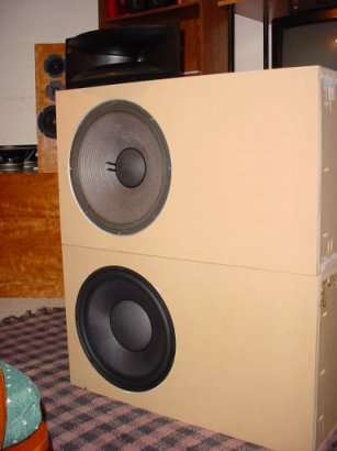
The big project right now is putting the new
boxes together. A friend and I cut up 5 sheets of MDF on Sunday and
covered his entire driveway with dust. Good thing we had masks. I spent
the afternoon on Monday routering out the 16 braces for the boxes.
The exterior dimensions are H 19" x W 21" x D 27.5" , Interior H 17.5" x
W 19.5" x D 26". Each box has 4 vertical braces also made of 3/4" MDF
with 50% of the area removed. Volume right now will be 4.84 cu ft before
considering driver volume.
I also built a horn enclosure with dimensions H 13" x W 21" x D 26".
This enclosure should function for the 2380 and Mr Widgets horn once it
arrives.
Now I have to get some ports. If we tune to 27Hz this driver wants 2-4"
ports or 1-6" port to keep wind noise down. Based on some rough
calculations with a 108 liter box it looks like dual 4" ports would be
19.6" long. A 6" port appears to be too long to fit in the box without
hitting the driver.
Once we subtract the port volume and driver motor volume these huge and
heavy boxes are down to close to 4 cu ft.
|
|
|
|
March 18 -
TimG
I now have T/S specs on multiple JBL
drivers. I used SoundEasy with the Constant Current method. The setup
consisted of the Delta 410 soundcard feeding the test signal to an
Harmon Kardon 795i receiver. The output from the receiver to the
speakers being tested was via 14ga Sound King cable around 6' long. The
input to the sound card from the BESL test jig, and to the receiver from
the sound card, was via 12' Radio Shack Gold Series RCA cables. The test
jig used the 18" shielded RCA cable that was included with the BESL jig.
The positive end of each RCA terminal was terminated with 47.5 Kohm
resistor and Radio Shack soldered alligator clips. I used a Metex ME11
multimeter to measure impedance and to determine the actual impedance of
my test resistor. The actual test resistor is a 400ohm, sand cast 10%, 5
watt resistor. I checked the impedance with a 400ohm, precision wire
wound, .05%, 1/4 watt resistor.
Here are the TS specs for the first 1500AL that was measured. This
driver was measured using the delta mass method using 100g of nickels
for the added mass. The rest of the drivers will be measured tonight
before break in and then all drivers will be broken in and then
remeasured using both the delta mass and delta volume methods. The
process for each driver takes only a few minutes, not counting time
necessary to mount the drivers in the test box.
Re=5.3 ohms
Fs=30.52 Hz
Qm=11.5176
Qe=0.3339
Qt=0.3245
Vas=208.99 L
Mms=143.71 g
BL=20.92 N/A
no=1.217 %
SPL=93.05 dB
Le=2.40
Effective diameter was entered as 33.66 cm by including half of the
surround on each side. If anyone has a better number for this parameter
let me know.
|
|
|
|
March 19 -
TimG
I took some quick
measurements with my laptop system, but I can't post images from that
computer. I'll be dragging my desktop system out to the garage on Sunday
to take some real measurements with my SoundEasy system and microphone
preamp. I will shoot some 1M response curves on and off axis for a
single woofer, MTM, and TMM array using the 1500ALs mounted in 4 cu ft
sealed boxes. I can carry all my other woofers around in one hand but
these things are just freakin monsters. My other woofer, that would be
my puppy, gets upset when I play with these things because I won't let
her in the same room when these $750 drivers are lying on the floor.
Would that be called woofer envy?
I really like my new measurement system and would recommend it. If you
want to get a Delta 410 sound card, buy one now before all the vendors
run out. The M-Audio Revolution 7.1 may work but I can't find anyone who
has tested it out yet. The Firewire 410 should work for a nice portable
system, but the reviews of this product are mixed. Apparently version
9.0 of Soundeasy is going to have an even more powerful measurement
system built in. Here, again is the parts run down for those wishing to
set up their own system:
PC Celeron 1700, Windows XP Pro, built by me
(SE 9.0 will require P4 2.66Ghz with 512 MB RAM)
SoundEasy 8.0 $210-225 now on sale at PartsExpress
M-Audio Delta 410 Soundcard $116
BESL microphone preamp $113
Radio Shack Gold Series RCA cables 12' $20 each
400ohm resistor $.25
Radio Shack alligator clips in a rainbow of colors
Metex ME11 digital multimeter, no longer available, but RadioShack
offers an true RMS multimeter for $69.99 22-186
Kim Giardin calibrated Panasonic capsule microphone $35
You also need an old receiver or a fancy preamp and amplifer to provide
a clean source of power for testing
|
|
|
|
March 21 -
TimG
The new prototype cabinets are done except
for the front baffles. They measure 21" wide x 19" high by 27.5" deep. I
need to know if I can recess mount the woofers 1/4" from the edge or
whether I need to leave more space for the horns to overlap the woofer
cabinets. The frames of the 1500ALs are 3/4" deep and 15.25" in
diameter. The front baffles are laminated 3/4" MDF and are 1.5" thick
with a 14" hole in the inner layer and a 15.25 hole in the outer layer
to allow the driver to be flush mounted.
I have cut wood for a horn frame that will have an open back and will
accept multiple horn sizes by swapping the front plate. It is 13" high
to accept what earlier dimensions said the prototype horn could be at
its smallest.
If we end up using an TMM design, we may want to mount the supertweeter
to the rear of the midhorn, just like on the S9800. Is it to late in the
design stage to allow this type of option?
My first tests have used a JBL 2380 horn and a 6" x 16" biradial horn. I
have just been resting these on top of the tower boxes. The final
cabinets are going to be quite the shipment.
|
|
|
|
March 22 -
Mr. Widget
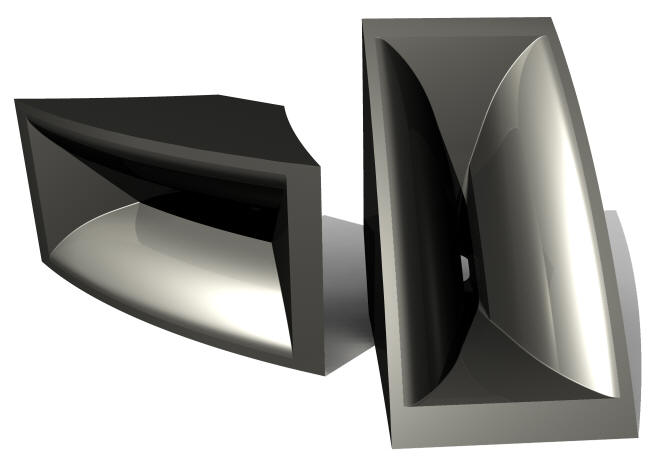
The initial horn(s) will be something like
the illustration below. They will require an 8" tall by 19(?)" wide
space to sit. I would expect the final horns to have a lip of some sort
to help incorporate them into the design. One possible scenario would be
to have the UHF horn incorporated into that lip.
No it is not too late to consider the option of having a recessed UHF
horn if the design ends up being TMM.
|
|
|
|
March 29 -
TimG
Everything was looking so good on Thursday, I was thinking I would have
measurements posted that night. If only it were so easy. The 4 cubic
foot boxes were basically complete, except for front baffle mounting and
binding post install, after just 2 Sundays with a helper. I spent the
afternoon stopping at 4 stores (Home Depot, Lowes, Radio Shack, and
Performance Audio) just to get the supplies I needed to wire up the 4
new boxes, secure the fronts, install t-nuts and remount the front
baffles. Now that I have the drivers mounted I can barely lift these
things. They have to be 100lb each at this point. On a positive note,
they are really solid and don't have a lot of obvious resonance.
Finally I have some measurements we can look at. I'm continually amazed
at how powerful SE is. My main computer, with the video capture program,
fancy sound card, and SE is downstairs hooked up to the test rig, so I
can't post the pictures until I bring it back upstairs. I need to get
some more measurement done while everything is in place so I'm not
willing to move it yet. What I will accomplish today is getting plots
for the MTM off-axis. If I can I will also get plots for the TMM option,
but all of this stuff is taking 4 times longer than I previously
estimated because I'm doing it all by myself. Surprising, I got my wife
to help me haul (4) 100lb cabinets across the yard, onto the porch, and
down the stairs without screaming. Unfortunately I had to do 6 hours of
yard work in return.
Things will start happening a lot more quickly now that everything is in
place. I say we worry about box tuning after we decide on the design
format. I will post the plots as soon as I can. Plan on seeing some
tonight.
Here are some things I learned:
1) It would be nice to have an indexed volume control on my test
receiver so that I could replicate volume levels on different days.
2) Don't try to use a fancy surround sound preamp for testing, it's to
much of a PTA to turn off all the features you don't need.
3) Use lots of masking tape to mark the position of your microphone
stand on the carpet so you can remember where it was before you had to
move it to do the close-miked woofer response.
4) Heavy things move a lot faster when you have 2 people to do it. (I
had to take Soma last night, and luckily my back felt undamaged this
morning.)
5) Always buy more wire than the amount you were certain would be more
than enough.
6) Next time invest in a computer power supply with an ultraquiet fan if
you plan on using it for testing, the mic picks up everything
7) 1 watt in a large format compression driver is lots.
|
|
|
|
March 29 -
TimG
OK, I have the MTM plots.
I'm not going to do TMM plots tonight because once I take the MTM apart
I'm not lifting that top box 50" off the ground again without help or a
hoist. I wish they would have used Neodymium on the motors for these
beasts I have on axis, 15 and 30 vertical. I will do the same for
horizontal, but MTMs don't suffer comb filtering in the horizontal
plane. These plots were taken to confirm the model so I don't think
there is a need at this time to do plots every 5 degrees.
There are limitations to these plots because I don't currently have
access to an auditorium. I'm limited to far field measurements above
about 350Hz. These plots do not include near field response because I'm
not sure what 15 degrees off axis looks like when the mic is almost
touching the dust cap. Basically adding the near field would raise the
level of each of the plots by the same amount.
The procedure for getting the complete far field picture is as follows.
Measure far field, move mic adjacent to dust cap, lower output level and
measure near field, add baffle gain to nearfield plot, adjust level of
near field to far field at 500Hz, merge near field to far field at
500Hz.
To obtain accurate far field response to a lower frequency I would need
to move the speakers and measurement system to a larger room. Since my
garage is only a 1 car, that won't really help. If I had a crane in my
back yard, and it was totally silent outside, I could measure the
speakers in my back yard, but neither of those conditions can be met. If
I am able to reserve the University Social Science Auditorium in May,
for the DIY event, I will be able to take accurate measurements to a
lower level, but I'm hoping to have estimates for the crossovers before
then, so it would just be for confiratory purposes.
The procedures I am using for measurement were obtained from Joe
D'Apollitos book, the SoundEasy manual, the LspCAD manual and the
SoundEasy user guide, which is an invaluable time saving resource
written by John K.
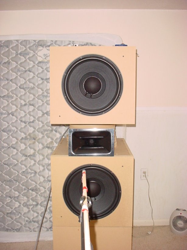
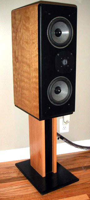
The image of the setup in my next post shows the woofer cabinets, 4 cu
ft internal, with 19" x 21" baffles. The drivers are 1500AL with a
reversed cabinet serving as a stand at the bottom. The cabinets are
separated by a 8.25" high stack of MDF round cutouts and the horn is a
DDS 1" throat 70 by 40 degree horn that I'm borrowing to test a new
compression driver. It looks like it would make a great horn for a 12"
or 10" midrange crossed over at 1000-1300Hz. I have not
yet had a chance to complete the horn baffle/spacer that will house the
H9800 horn.
|
|
|
|
March 31 -
TimG
What are those curves telling us??
The curves show some of the comb filtering effects that occur with an
MTM with large woofers and a wide center-to-center distance. I
previously modeled the comb filtering effects in another program and
posted the results. I will do that modeling again now that I have more
information about baffle size and correct piston diameter so that we can
compare the predicted to the measured results. Unfortunately, I can
model more of the comb filtering effect than I can measure. However, the
software predictions match reality very closely and are based on vector
modeling. Therefore, I feel we can trust the predicted results because
they will correspond to the actual results. That is not to say that the
final crossovers will not be tweaked by ear.
I have measured TS parameters of the woofers, and I will conduct on an
off-axis measures of the 1500ALs in both a MTM and TMM format so that we
can decide on the advantages and disadvantages of each design before
moving on with the design process.
I have another microphone that I can use, but I don't have a calibration
file for it. My Panasonic capsule mic is the same device used in the
Mitey Mike. The reference speaker is a good idea. I will shoot some
measurements of my reference speaker today. My current reference is a
4-way based on the NHT 3.3. The 3.3 is no longer in production but it is
a 4-way based on a 12", 6.5", 4", and 1" dome tweeter. Kind of like a
sealed L250ti. Here is a link to a review of its little brother the 2.9.
http://www.stereophile.com/loudspeakerreviews/320/
A friend is also planning to bring over his
Focal W-cone version of the Joe D' designed Aria 7 MTM tonight. Here is
a link to what they look like. We can measure these too.
http://www.zalytron.com/pictures/Focal6WTC120.jpg
An RTA measurement in this room would be totally colored by room
reflections. Gated response measurements are used so room reflections do
not contaminate the measurements. In a sense, gated measurements, merged
with close mic woofer measurements simulate measurements under anechoic
conditions. I can take an ungated measurement of the speaker, but I'm
not sure what value it would have. We certainly don't want to design the
crossover based on measurements that include room reflections from my
small room. However, this issue merits more discussion. Here are just
some of the issues involved that we should discuss.
1) You can design the speaker to measure flat at one point in the room,
on the listening axis, or use EQ to achieve the same result. However it
may sound terrible at every other point in the room, and will not be
accurate in any other room.
2) On the other hand, you can design the speaker to have flat frequency
and power response under simulated anechoic conditions and then treat
your listening room to achieve good response at the listening position,
with small tweaks to the crossover as necessary, (i.e., for high
frequency rolloff contouring or a BBC dip). This type of speaker has the
potential to sound excellent in all rooms, with some work.
I would lean towards the second design philosophy, with the provision
for EQ in the bass frequencies (say below 100Hz) since this is the area
of response most affected by the room. This is the same design
philosophy used in the JBL LSR6300 studio monitor series, and the
Infinity Prelude speaker before that. I personally feel that this is the
best way to produce a SOTA speaker, and it is also the future of
accurate audio reproduction. However, this philosophy would likely
involve having to mount the subwoofer separate from the main speakers to
produce the best wide range response, not always the most decor or space
friendly solution.
Please refer to the white papers located here, particularly the "RABOS"
and "Loudspeakers and Rooms" technical papers:
http://www.infinitysystems.com/homeaudio/technology/technology_whitepapers.aspx
and here
http://www.jblpro.com/LSR/PDF/White%20Papers.pdf
A similar philoosphy is used in the new B&O
BeoLab5
http://www.bang-olufsen.com/graphics/bogo/media/LOUDSPEAKERS/BeoLab5/BeoLab_5_Technology.pdf
The reference axis of this speaker is at 42.125" from the floor. The
horn shown in the picture will have nothing to do with the final design,
was not hooked up, and is just be used for my own evaluation purposes. I
have used the cabinets I have available to try to get the axis at the
midpoint of my rooms vertical height to allow for the longest time of
flight to the mic before floor or ceiling bounce enters the picture.
Mr. Widget originally estimated that the closest we would be able to get
the woofer center-to-center distance was 28.25 inches. Others mentioned
an MTM with 36 inch center-to-center spacing, but I think the
simulations have already demonstrated that we want to get the woofers as
close together as possible for an MTM. I have been recently informed
that the mid horn will have to be at least 8" high, but I have not
received word yet on how much vertical space the supertweeter will
consume.
I don't think I know Don's seated ear height. If I did, I have forgotten
it. I would shoot for a mid horn height of around 39-42" depending on
the final design. This height can always be adjusted by adding
provisions for tilt and level on the final industrial design cabinets.
|
|
|
