|
|
|

|

|
September 2004
|
|


|
PROJECT MAY
Sponsored by

®
|
|
|
|
September 4
-
Mr. Widget
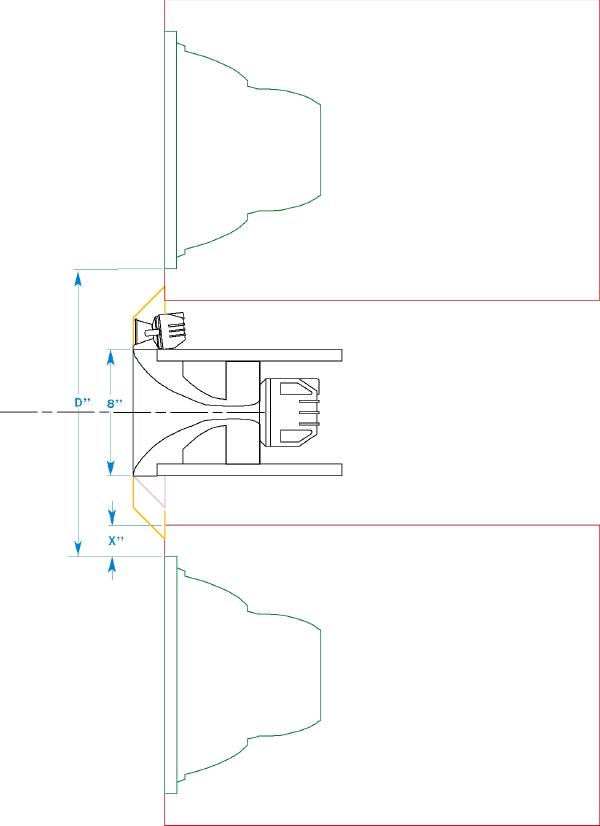
I have started working on the Sonoglass
composite HF-UHF horn. I have a few questions for Tim and the crew.
From Tim, the mdf prototype box exterior dimensions are H 19" x W 21" x
D 27.5"
Based on that, if the woofer is centered top to bottom there is just
under 2" for the distance labeled
X.
Tim, is this correct? I
would also like to know what the distance
D
has been in your
tests. Additionally I need to know what the distance has been between
the top surface of the lower woofer cabinet and the bottom of the top
one. In this drawing there is 14". For the final design we can bring
them in closer, but only if there is a cavity in the top box to
accommodate the 045Be. A distance greater than 14" will make the
prototype easier to deal with, but I assume we would like
D
to be
as small as possible.
I am placing the two woofer boxes symmetrically about the centerline of
the mid horn. Does anyone have objection with that? It could also be
centered about a mid point between the H9800 and the 045Be.
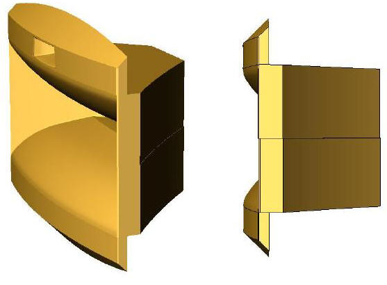
Here are a couple of rendered sketches to
help people picture what the horn will look like. I have used the MDF
horn drawing instead of an accurate Sonoglass H9800 as I don't have one
drawn up and it would be a bit of work. I think you can get an idea about what I am
proposing though.
|
|
|
|
September 4
-
Mr. Widget
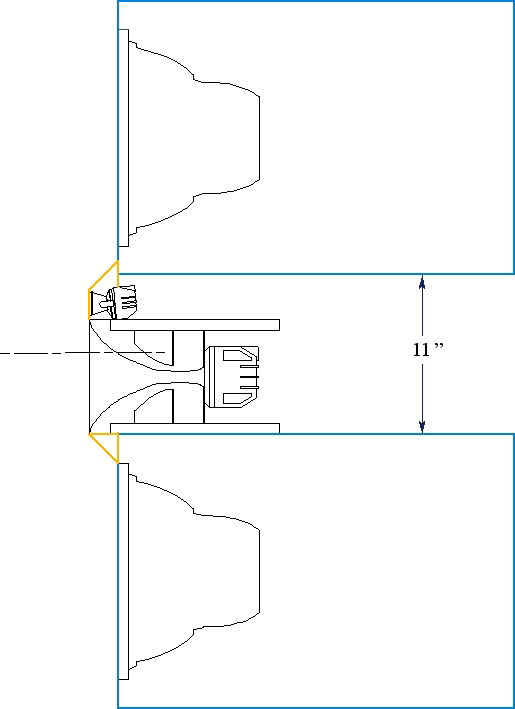
Here's another option. This drawing shows an
asymmetrical baffle treatment and puts the woofer center line as shown
by the dashed line, but it does put the woofers closer together at 30"
center to center. As the drawing shows the woofer cabinets are 11"
apart. It would be possible to make the baffle lip symmetrical but that
would separate the woofers by two more inches.
|
|
|
|
September 7 -
TimG
I would vote for making the horn assembly
symmetrical so the midrange driver is centered in the MTM. If we need
the woofers closer together I could eventually build some new baffles
for the prototype boxes that allow the drivers to go to the edge of the
box. It's not really an MTM if the tweeter isn't in the middle (ignoring
the 045 for convenience).
|
|
|
|
September 7
-
Mr. Widget
Moving the woofer to the edge won't change
much as the chamfered area above the horn uses up most of the space.
I will make the composite horn rig symmetrical and build it as tight as
possible. It will probably yield a test set up where the woofers are
just under 32" center to center.
|
|
|
|
September 7
-
Giskard
I just received the low pass and high pass
filter components today and could begin building either in the next few
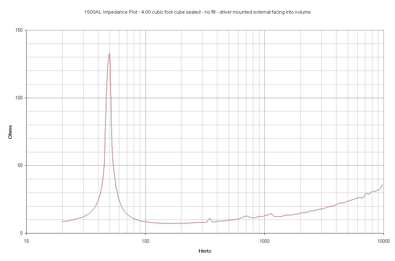
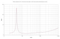
days. I have yet to order the bandpass. Just for fun - here's the 1500AL
mounted in a 4.00 cubic foot sealed test cube. One should note the
standing wave at ~ 350 Hz.
The standing wave can be
seen in the impedance curve. It is the blip at ~ 350 Hz. With the
oscillator set at that frequency the most horrid sound emanates from the
system as would be expected. The internal dimensions of the enclosure
are 484 mm cubed.
|
|
|
|
September 11
-
Giskard
The addition of 2" thick OC fiberglass on
all panels is sufficient to reduce the standing wave ~ 350 Hz. Impedance
drops to "normal" and the objectionable sound is greatly attenuated.
This doesn't necessarily have anything to do with the project. I just
thought it might be interesting to some that the standing waves
generated in a cube are definitely objectionable and are viewable in an
impedance run.
Some closed box data:
driver mounted normal
4.0 cu ft gross
no fill
Qtc = 0.56
Fc = 49.8
driver mounted normal
4.0 cu ft gross
2" OC fiberglass on all panels except baffle
Qtc = 0.54
Fc = 47.8
|
|
|
|
September 12
-
Giskard
I ran the TS parameters using BB6P just for
fun and here is what I got.
One can recreate the whole thing by using the \Test\Driver feature and
entering the following:
Manufacturer: JBL
Model Name: 1500AL
Serial Number: 1500AL-01686
Resistor: 982 ohms
Piston Diameter: 13.18 in
Voice Coil Resistance (Re): 5.4 ohms
Voltage (V1): 10.04 volts
Frequency (Fs): 27.9 Hz
Voltage (V2): 1.514 volts
Frequency (F1): 21.4 Hz (.289 volts)
Frequency (F2): 39.5 Hz (.289 volts)
Volume (Vb): 4.195 cu ft (includes inverted cone volume and enclosure
cutout volume)
Frequency (Fc): 48.0 Hz
Voltage (V2): 1.47 volts
Frequency (F1): 40.7 Hz (.285 volts)
Frequency (F2): 58.3 Hz (.285 volts)
results
Mechanical Parameters
Fs = 27.9 Hz
Fc = 48 Hz
Qms = 8.072
Qmc = 14.07
Vas = 248.6 liters
Cms = 0.226 mm/N
Mms = 0.144 kg
Rms = 3.128 mohms
P-Dia = 13.18 in
Sd = 880.2 sq.cm
Electrical Parameters
Qes = 0.305
Qec = 0.549
Re = 5.4 ohms
BL = 21.13 N/A
Electromechanical Parameters
Qts = 0.294
Qtc = 0.529
no = 1.704%
1-W SPL = 94.46 dB
|
|
|
|
September 13
-
Giskard
They "look good" in 4.0 to 5.0 cubic foot
volumes tuned to ~ 28 Hz.
This volume/tuning should respond very well to room placement and/or EQ.
Just a few dB at 28 Hz should do wonders in the right room.
It is easy to see why Tim thinks sealed sounds decent too. I would
imagine room gain would fill in the bottom nicely. Again, a few dB of
VLF/LF EQ with the sealed system could be very interesting. Excellent
transient character!
I have yet to determine the port length for the prototype boxes for this
tuning. I did unpack one this weekend to look at it. It sure isn't as
thick as a cardboard mail tube or PVC pipe. I'm holding off cutting the
requisite holes in the box until I do a few more 15" driver measurements
(1500SUB, 2234H, and 2235H).
I also worked on the low pass filter mounting boards. I hope to have the
low pass filters built and shipped to you by the weekend. No switches,
you will need to change the damping by hand. I'll include the extra
resistors which easily screw into the terminal strips. I'll have the
default damping already installed. I'd like you to do sealed box
measurements with the filters first before venting the enclosures. All
the components on the boards attach via terminal strips and tie wraps so
all the components are easily removed and replaced. Very "prototypical"
as opposed to PC board mounted and such.
|
|
|
|
September 22 -
Giskard
I
have received all the inductors, capacitors,
and resistors for the prototype networks as of last night.
Big, heavy, expensive, TOTL stuff...
I'm going to go looking for nylon bolts and brackets today.
|
|
|
|
September 29 -
Giskard
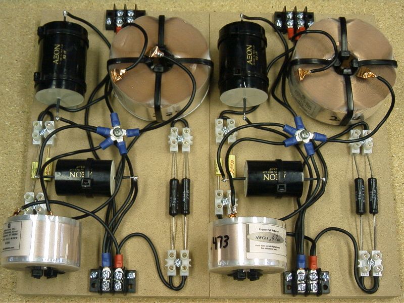
Here are the finished low pass network
prototypes. With a 3.9 ohm dummy load minimum impedance is 3.8 ohms. The
large "cheap" capacitors are bypassed with polypropylene & foil and
polystyrene & foil capacitors. These bypass capacitors are easily
unhooked for listening tests, with and without, to hear the effects with
the dual 1500AL transducers. The Mills resistors are set for maximum
damping for flattest LF response
|
|
|