Page 9 of 12 FirstFirst ... 7891011 ... LastLast
Results 121 to 135 of 171

Thread: Help With Potential DIY Project

  1. #121
    Senior Member
    Join Date
    Apr 2007
    Location
    Maryland
    Posts
    481
    Quote Originally Posted by 4313B View Post
    I went with the blue and it looks outstanding.

    I used the second formula in the link below scaled down to a quart and didn't lighten it.

    JBL Blue Baffle Paint
    4313B,

    Thank you so much for posting that link. I went ahead with the Behr mix. After I had the technician at Home Depot prepare the paint, I want to inspect it one more before walking out the door. Just like the originator of the Behr paint mix, I too found the color too dark for my liking. Hence, I asked the technician to pour 2oz of white paint to the mix. After adding 2oz of white, the resulting bule was just the blue I wanted for my DIY 4345.

    Thanks once agian,
    D

  2. #122
    Obsolete
    Join Date
    Apr 2003
    Location
    NLA
    Posts
    12,193
    Cool!

    Yeah, it is darker without the white added; I prefer the darker myself.

  3. #123
    Senior Member
    Join Date
    Apr 2007
    Location
    Maryland
    Posts
    481

    Veneering Question

    I am getting ready to veneer over the next few days (hopefully Thursday). Does anyone have any helpful tips before I start the process? More specifically, I wanted to know what I should be worrying about in regards to the tempreture in the room, the humidity, etc. Given the fact that I have brought the enclosure in from the garage - I have better control of the climate.

    Just a reminder, I will be using the iron-on method of veneering.

    Thanks

  4. #124
    Senior Member
    Join Date
    Apr 2007
    Location
    Maryland
    Posts
    481

    Crossover Question


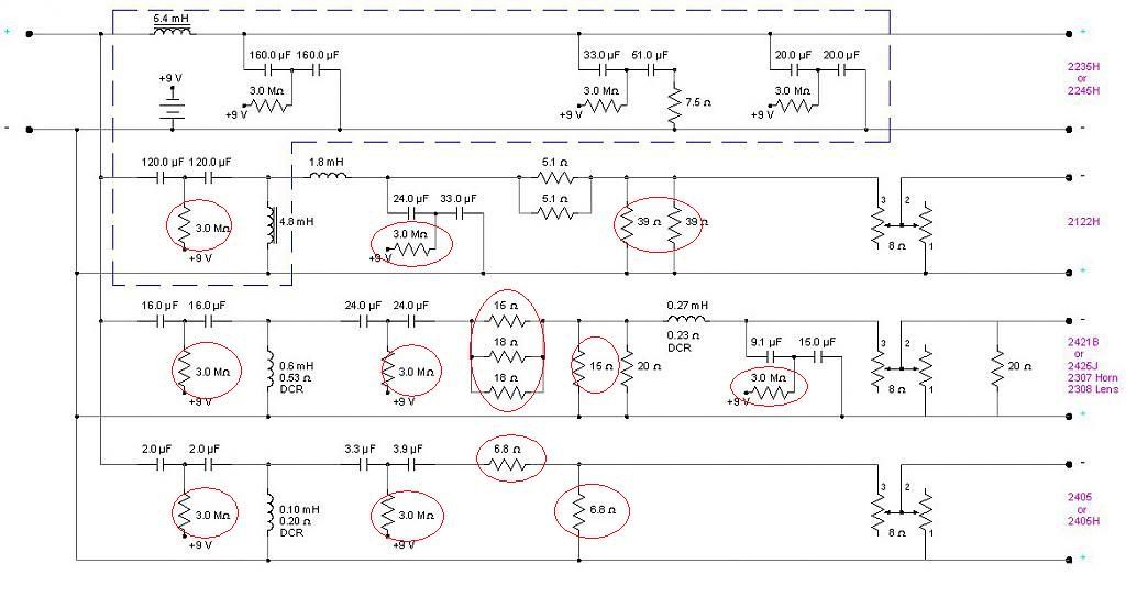
    Have few crossover questions. I am using the above schematics for my DIY 4345 build.

    I wanted to know where I can find the circled resistors. I checked Parts Express website for these components but they do not carry these exact values. Do you guys typically wire two resistors of different values in parallel to get actual value, or is it safe to use a 40ohm resistor for as a replacement for the required 39ohm resistor, and 20ohm as a replacement for 18ohm, 16ohm as a replacement for 15ohm, and etc. I am afraid of deviating too much from the schematics.

    Lastly, can someone please help me find the 3.OMohm resistors?

    Thanks,
    Dhar

  5. #125
    Senior Member grumpy's Avatar
    Join Date
    Oct 2003
    Location
    SoCal
    Posts
    5,743
    An example... with low quantity requirements.

    http://search.digikey.com/scripts/Dk...ame=3.0MQBK-ND

    Some of the power resistors (if of the same value in parallel)
    were likely used that way to dissipate more power.

    If they were paralleled but not the same value, I would -guess-
    that the value was carefully tweaked (possibly in combination with
    more power handling, but then the lower value part would
    take the heat).

    If there was a parts list, you might get a better idea of what
    was intended in terms of wattage and tolerance... or you might
    ask the designer nicely (not me), rather than me guessing.

  6. #126
    Senior Member John W's Avatar
    Join Date
    Jun 2004
    Location
    Renton, WA
    Posts
    593
    The 3.0M resistors that hook up to the 9v battery are used for charge coupling the capacitors. These only need to be the 1/4 watt variety that you find at electronic suppliers like mouser.
    If you can't find the values you need at Parts Express, here is a link to another supplier of Mill resistors like you would find in a crossover. You would probably want the 12 watt rating. http://www.soniccraft.com/mills_resistors.htm
    Like mentioned, you can also parallel the values. A pair of 39 ohm 12 watt resistors, would be the same as a single 19.5 ohm 24 watt resistor. The doubling in this instance is for the extra power rating.

    Do a search on-line and I'm sure you can find a calculator for determining parallel and series resistor values.

  7. #127
    Senior Member
    Join Date
    Apr 2007
    Location
    Maryland
    Posts
    481
    Quote Originally Posted by John W View Post
    The 3.0M resistors that hook up to the 9v battery are used for charge coupling the capacitors. These only need to be the 1/4 watt variety that you find at electronic suppliers like mouser.
    If you can't find the values you need at Parts Express, here is a link to another supplier of Mill resistors like you would find in a crossover. You would probably want the 12 watt rating. http://www.soniccraft.com/mills_resistors.htm
    Like mentioned, you can also parallel the values. A pair of 39 ohm 12 watt resistors, would be the same as a single 19.5 ohm 24 watt resistor. The doubling in this instance is for the extra power rating.

    Do a search on-line and I'm sure you can find a calculator for determining parallel and series resistor values.
    Thanks for posting John.

    I guess my question is whether these values need to be exact or not.

    For instance, the crossover requres a 6.8ohm resistor. Would it be okay to use a 7.0ohm resistor as a replacement? And would it okay for me to use 20 ohm resistor as a replacement for the required 18ohm resistor <-- Or should I wire a 16ohm resistor (which they have available) and 2ohm resistor (again, availalbe) in series to get a total resistance of 18ohm?

    And Lastly, do I really need the Mills resistor, or can I use Dayton which are 1/3 the price?

    Thanks
    D

  8. #128
    Senior Member
    Join Date
    Feb 2008
    Location
    Ashland, MA
    Posts
    908
    Quote Originally Posted by dkalsi View Post
    I am getting ready to veneer over the next few days (hopefully Thursday). Does anyone have any helpful tips before I start the process? More specifically, I wanted to know what I should be worrying about in regards to the tempreture in the room, the humidity, etc. Given the fact that I have brought the enclosure in from the garage - I have better control of the climate.

    Just a reminder, I will be using the iron-on method of veneering.

    Thanks
    Yeah: Do a LOT of legwork (searching the archives etc) before beginning. The more reading you do, the easier the task. Also, go slowly (naturally, steps where you need to move quick for the adhesive don't apply) and stop and think before each step. A lot of people think they're "In the zone" when they're really just compounding errors (ask me how I know!)

    There are a lot of ways to veneer, so I won't get too much more specific. With appropriate care you'll do fine.

  9. #129
    Administrator Mr. Widget's Avatar
    Join Date
    Apr 2003
    Location
    San Francisco
    Posts
    9,741
    Quote Originally Posted by dkalsi View Post
    And Lastly, do I really need the Mills resistor, or can I use Dayton which are 1/3 the price?
    You can use the Daytons... I don't because resiters are cheap, but I doubt you'll notice a difference.

    As for values... I try to end up with measured values that are within 5% of the spec... nice thing about the Mills is that they are almost always spot on. Most of the inexpensive resisters will vary a fair amount.


    Widget

  10. #130
    Senior Member grumpy's Avatar
    Join Date
    Oct 2003
    Location
    SoCal
    Posts
    5,743
    a little more on values...

    1) in circuits where there they form a fixed/resistive attenuation pad, using values
    that are reasonably close, is probably fair game, especially if followed by an
    L-pad in the design.

    2) in circuits where the resistors are used to obtain a certain frequency
    response shape or Q, I'd follow the recipe as closely as possible, -and-
    be sure that the L/R pairs match (or are tightly toleranced). Otherwise,
    you may deviate from (lose) the intended system voicing.

    I've used the ceramic/wire-wound Daytons... sound fine to me, but the
    crappy gold plating means only bend the leads if you have to, or only do it
    once.

  11. #131
    Administrator Mr. Widget's Avatar
    Join Date
    Apr 2003
    Location
    San Francisco
    Posts
    9,741
    Quote Originally Posted by grumpy View Post
    a little more on values...
    Very good points.


    They gold plate the leads? That's pretty cheesy.

    A bit OT:

    The other day I was digging through my interconnect bucket and got a laugh... I noticed some old "gold plated" RCAs on a cheapo pair had turned rather brownish... I wonder what the percentage of gold their plating was? Or perhaps they advertised their interconnects as gold colored?


    Widget

  12. #132
    Senior Member
    Join Date
    Feb 2008
    Location
    Ashland, MA
    Posts
    908
    Quote Originally Posted by Mr. Widget View Post
    Very good points.


    They gold plate the leads? That's pretty cheesy.

    A bit OT:

    The other day I was digging through my interconnect bucket and got a laugh... I noticed some old "gold plated" RCAs on a cheapo pair had turned rather brownish... I wonder what the percentage of gold their plating was? Or perhaps they advertised their interconnects as gold colored?


    Widget
    Generally that's the brass peeking through, in its lovely oxidized state

  13. #133
    Obsolete
    Join Date
    Apr 2003
    Location
    NLA
    Posts
    12,193
    Quote Originally Posted by dkalsi View Post
    Lastly, can someone please help me find the 3.OMohm resistors?
    I use 2.2 M ohm myself but anything between 2.0 and 5.0 M ohm will work.
    Quote Originally Posted by dkalsi View Post
    I am using the above schematics for my DIY 4345 build.
    I'm working on a new one...

  14. #134
    Moderator hjames's Avatar
    Join Date
    Nov 2005
    Location
    NoVA - DC 'burbs
    Posts
    8,549
    Quote Originally Posted by 4313B View Post
    I use 2.2 M ohm myself but anything between 2.0 and 5.0 M ohm will work.
    I'm working on a new one...
    Thank you, sir ... eager to see your next design!
    2ch: WiiM Pro; Topping E30 II DAC; Oppo, Acurus RL-11, Acurus A200, JBL Dynamics Project - Offline: L212-TwinStack, VonSchweikert VR-4
    7: TIVO, Oppo BDP103D, B&K, 2pr UREI 809A, TF600, JBL B460

  15. #135
    Senior Member
    Join Date
    Apr 2007
    Location
    Maryland
    Posts
    481
    Quote Originally Posted by 4313B View Post
    I use 2.2 M ohm myself but anything between 2.0 and 5.0 M ohm will work.
    I'm working on a new one...
    Oh noo? - new crossovers? Should I cancel my order for the parts corresponding to the above schematics?

    Thanks,
    D

Thread Information

Users Browsing this Thread

There are currently 1 users browsing this thread. (0 members and 1 guests)

Similar Threads

  1. My Drew Daniel's inspired DIY project.
    By Baron030 in forum Lansing Product DIY Forum
    Replies: 48
    Last Post: 03-12-2012, 07:28 PM
  2. DIY JBL project K2-S7500 or K2-S9500
    By citadel in forum Lansing Product DIY Forum
    Replies: 7
    Last Post: 05-08-2011, 04:11 PM
  3. Altec "stonehead" DIY project
    By definitief in forum Lansing Product DIY Forum
    Replies: 8
    Last Post: 12-28-2006, 01:23 PM
  4. DIY project for 4312
    By Max in forum Lansing Product DIY Forum
    Replies: 6
    Last Post: 01-19-2006, 03:16 AM

Posting Permissions

  • You may not post new threads
  • You may not post replies
  • You may not post attachments
  • You may not edit your posts
  •