Page 8 of 10 FirstFirst ... 678910 LastLast
Results 106 to 120 of 148

Thread: CLIO Clinic

  1. #106
    Administrator Mr. Widget's Avatar
    Join Date
    Apr 2003
    Location
    San Francisco
    Posts
    9,745
    Quote Originally Posted by Robh3606 View Post
    What am I showing you?? Did you read the post??
    I read the portion addressed to me, but must admit I didn't read the bit to Zilch.

    Quote Originally Posted by Robh3606 View Post
    The windows are at 6, 9, and 15 Miliseconds. The top curve is the raw MLS measurement with 1/12 octave smoothing. You can clearly see the resolution getting progressively more washed out below 1KHz. Almost looks like what happens when you change over from 1/12 to 1/3 smoothing. The basic curve remains but the detail and resolution get lost.
    The detail and resolution don't get lost... the "detail" you are seeing is the noise caused by reflections in the room. Unfortunately looking at your impulse plot, there seems to be a heck of a lot of reflective information in your measurement.

    In my much larger room I can usually see a distinct first reflection. In this measurement taken some time ago of one of the Project May tests, you can see that I was close to the floor and could only get about 3ms of clean measurement before my first reflection at ~6.5ms... the initial delay of ~3.5ms is due to the digital latency of running the signal through my DEQX unit... in a typical measurement the impulse would start much closer to time zero. The only usable windowing for this measurement would be to place the initial cursor at the beginning of my pulse (inverted polarity in this case) and the beginning of the first reflection. With a window of only 3ms, the curve will not be terribly useful below maybe 2KHz.

    I have learned quite a bit about taking these measurements since this was taken... today I would set up the speaker system differently to get a much longer clean window.


    Widget
    Attached Images Attached Images  

  2. #107
    RIP 2011 Zilch's Avatar
    Join Date
    Jun 2004
    Location
    Berkeley, CA
    Posts
    9,963
    My impulse curves look like Mr. Widget's, but with a lot more "hash."

    Speed of sound is 13.56 in/ms, so being typically 1 M back, I get ~3 ms latency (delay) before the pulse.

    I can always see the floor reflection distinctly. When it appears depends upon the height of the DUT and the microphone at any given distance. I can usually knock that down to what I consider insignificance with padding on the floor. The differences in the FR curve are immediately apparent.

    If I'm trying to do critical measurements, I elevate the DUT to 1/2 the room height, about 5' here. In that situation, the floor and ceiling reflections occur at approximately the same time, and that's the limit of where I can set the end of the sampling window. (I'm not enough of a junkie to pad the ceiling.) That establishes the lowest frequency for which the measurement is valid, and while a theoretical frequency is computed and displayed in the legend, it's clear from the FR curve itself that some several-times multiple of that is more indicative of actual.

    I can achieve longer windowing periods (and thus resolve lower frequencies) by moving the mic further back from the DUT, since that also increases the distance (and time) for floor and ceiling bounces, but other room reflections increasingly pollute the impulse and FR result. Up to a point, those can be masked with smoothing, but so also diminishes the resolution of the FR curve result.

    For more routine screening measurements, I leave the DUT closer to the floor and squelch the floor reflection as best I can with a thick pad of insulation (it can be localized from the impulse curve,) thereby lengthening the window until the arrival of the next major reflection. The impulse curve may be stored on-screen as an overlay for comparison as other changes in the room are made to minimize contamination by reflections from other sources. On occasion, my coffee cup on the bench has been a meaureable culprit.

    Manipulating these variables, I can achieve useable results below 1 kHz; how much below depends upon the particular setup. Again, that's for "screening," and I have to apply a higher level of smoothing to filter out the resultant noise in the FR curve than with the better setup used for critical measuring. In neither case do I look for accurate results much below 1 kHz. If I want to see what's going on in a gross manner down there, I just click off the window, knowing the result to be inaccurate. The differences in the "accurate" area of the curve are quite apparent when that is done, so I know and appreciate the value of the quasi-anechoic MLS method.

    As indicated earlier, I'm not yet as familiar with how to manipulate the gating, delay, and resolution parameters in sinusoidal measurements to achieve an optimum result. Thus far, it's been no better than unwindowed MLS, so I use it primarily for impedance and distortion measurements, not frequency response.

    RTA continues to have considerable utility. There are many measurements and adjustments that are easiest and best accomplished interactively, in real time. I also use it to find the precise mic location "sweet spot" for full system response measurements with MLS, a technique I should probably document, as I have never seen it in the literature....

    Note to readers: Much of this discussion relates to making accurate measurements at the lowest possible frequency below 1 kHz. Results above 2 kHz are not at issue, for the most part. I believe all of us doing this would agree we can easily and routnely achieve reliable results in the upper (shorter wavelength) region of the frequency spectrum using MLS.

  3. #108
    Administrator Mr. Widget's Avatar
    Join Date
    Apr 2003
    Location
    San Francisco
    Posts
    9,745
    Quote Originally Posted by Zilch View Post
    Speed of sound is 13.56 in/ms, so being typically 1 M back, I get ~3 ms latency (delay) before the pulse..
    ...that's right. I wasn't sure what the conditions of that measurement were... but now on reflection, I am sure that the 3ms was due to the "time of flight" between the driver and mic. I just wasn't thinking it through... and it has been months since I measured anything and two years since I took that particular measurement. When DEQX is in the circuit the delay is even longer... and obviously so is the time of flight when a 2m measurement is made.
    Quote Originally Posted by Zilch View Post
    I can see the floor reflection clearly. When it appears depends upon the height of the DUT and the microphone. I can usually knock that down to what I consider insignificance with padding on the floor. The differences in the FR curve are immediately apparent.
    That's true, but even with an 18" high stack of Sonex, I can get the higher frequencies to "clean up" nicely, but the Sonex is invisible to lower frequencies... for the lower frequencies to be accurately measured there is no substitute to increased distance between the loudspeaker and the floor or other object of first reflection.


    Widget

  4. #109
    Administrator Robh3606's Avatar
    Join Date
    Apr 2003
    Location
    Rocinante
    Posts
    8,213
    The detail and resolution don't get lost... the "detail" you are seeing is the noise caused by reflections in the room. Unfortunately looking at your impulse plot, there seems to be a heck of a lot of reflective information in your measurement.
    Hello Widget

    The resolution does indeed get lost. Here are articles on measurement and the effects of widowing. JBL/Harmon went to a lot of expense to build a large anecholic chamber for this very reason. What's going on with my measurements is independant of that.

    http://stereophile.com/features/105kh/

    http://www.harman.com/wp/pdf/AudioScience.pdf


    Take a closer look at the scales. I am zoomed in a decade lower in my resolution. If I scale the plot in the same resolution as yours the "noise" goes away. The reason I did that was to find the first reflection. When you get in close at lower power measurements, under a watt, it's difficult to see them. My thoughts being that lower SPL means lower level reflections. I also did this measurement well away from everything right smack in the middle of the room to try to minimize reflections. Yes there is a higher noise level but there is always some noise in any measurement we do. Noise doesn't necesarilly translate as reflections. Have you been using CLIO for in room measurements?? If so what have you been doing??? I have been trying to figure out ways to try to extend the lower useful range without going outside. Do have any ideas along those lines???

    Rob
    Attached Images Attached Images  

  5. #110
    Obsolete
    Join Date
    Apr 2003
    Location
    NLA
    Posts
    12,193
    Quote Originally Posted by Robh3606 View Post
    I have been trying to figure out ways to try to extend the lower useful range without going outside. Do have any ideas along those lines???
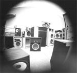
    Gymnasium and a ladder. JBL uses a large room kind of like a small elementary school gymnasium.

    Here are a couple of pictures of lifts in the rooms. In the second picture the lift is pointing towards an empty corner of the room.
    Attached Images Attached Images   

  6. #111
    Obsolete
    Join Date
    Apr 2003
    Location
    NLA
    Posts
    12,193
    Quote Originally Posted by Robh3606 View Post
    I don't think the neighbors will like that at 3AM. I have two major roads less that 1/4 mile away plus overhead airport traffic depending on the runways used. Outdoors sure would be nice!!
    I really don't know what to say. Just do the best you can I guess.

    JBL still uses this for ground plane measurements but the neighbors often complain regardless of the hour of day (loud levels to get a decent S/N). There is a system being measured to the left in this picture but we were not allowed to shoot a picture of it. I would have liked to have had a picture of the rig to show. The woman doing the measurements was in a small shack just beyond the SW corner of the picture.
    Attached Images Attached Images  

  7. #112
    Administrator Robh3606's Avatar
    Join Date
    Apr 2003
    Location
    Rocinante
    Posts
    8,213
    Gymnasium and a ladder. JBL uses a large room kind of like a small elementary school gymnasium.
    Hello Giskard

    Thanks for the pictures!! Now that's a room!!! Well that's an idea. I am not portable though and I can't see getting a lap top so I am kinda stuck for now. Here's a crazy thought for you. You use an anecholic chamber so the speaker see's open space and all reflections are absorbed. I have been wondering if you can use noise to accomplish the same thing. If your reflections are very low level and get lost in the backround "noise" so you can't see them isn't that in essence the same thing?? You would need a pulse large enough so the software could discriminate it from the noise but you see where I am going with this?? Go very low level so they "get lost". I figure the lower the level of the reflections the less influence they have on the measurements. So do you think I am nut's or what???

    Rob

  8. #113
    Obsolete
    Join Date
    Apr 2003
    Location
    NLA
    Posts
    12,193
    I don't think you will be able to get a decent S/N doing that.

    Try what Westlake does. Ken and Edgewound posted some pictures of their measurement rig.

    Anechoic chambers are not all that fun to be in.
    Attached Images Attached Images  

  9. #114
    Administrator Robh3606's Avatar
    Join Date
    Apr 2003
    Location
    Rocinante
    Posts
    8,213
    Thanks I will go take a look. I need to hit the books I guess. I am wondering what the consequences are with a higher S/N and what to look for. Just wondering what minimum would be still give useful measurements.

    Rob

    Last edited by Robh3606; 03-18-2007 at 08:50 AM. Reason: Added photo

  10. #115
    Administrator Mr. Widget's Avatar
    Join Date
    Apr 2003
    Location
    San Francisco
    Posts
    9,745
    Quote Originally Posted by Robh3606 View Post
    The resolution does indeed get lost. JBL/Harmon went to a lot of expense to build a large anecholic chamber for this very reason.
    Of course you are right.... but what I meant was that a properly time windowed MLS measurement always looks rather smoothed... and if it isn't smooth it means it has noise artifacts from reflections... now your very close horn measurements do indeed eliminate most of the room's effects so that is a different animal. I'll look into this some more soon...

    Quote Originally Posted by Robh3606 View Post
    Take a closer look...
    I will... but I've got to run. I need to take a series of measurements later today or early this week anyway so I'll check out what I get when I place the mic at the horn bell and then at distance.


    Widget

  11. #116
    Senior Member
    Join Date
    Apr 2003
    Location
    Australia
    Posts
    7,956
    Rob,

    I think it would depend on the reverberation time of the measurement environment at the frequencies you are looking at. I mean if your room hangs for a bit at those frequenies you are going to have a hard time working out what is no matter what you do. Try a search on tube traps. There is a lot of stuff you can do to remedy the situation. It may seem crude but large absorbent bat above and below the subject under measurement makes a bit of an improvement.

    I have heard of driver frames resonating and the way drivers are clamped to a baffle causing odd peaks and spikes so go figure.

    If you are not confident of the setup it makes it difficult.

  12. #117
    Senior Member
    Join Date
    Apr 2003
    Location
    GTA, Ont.
    Posts
    5,111
    Hello CLIO Club,

    - I really like this LSPcad ( or is it PRAXIS ??? ) generated image belonging to "Too Tall" . I like it because of the included info on Acoustic Phase .


    - Also, I noticed that Jack Bouska posted some images / though quite small / that pertain to acoustic phase . They are within his DIY thread ( highlighting his large MTM system ) with the thread being located here !


    - The above image was generated by his ETF software .

    - Does CLIO also generate an Acoustic Phase readout ? ( I don't think I've ever seen one . )


    Thanks < .Earl K

  13. #118
    RIP 2011 Zilch's Avatar
    Join Date
    Jun 2004
    Location
    Berkeley, CA
    Posts
    9,963
    Quote Originally Posted by Earl K View Post
    Does CLIO also generate an Acoustic Phase readout ? ( I don't think I've ever seen one . )
    Yes, and it's just a button click to show it alone or superimposed, wrapped or unwrapped, as desired....

    I don't post it 'cause I don't yet understand it....

  14. #119
    Senior Member
    Join Date
    Apr 2003
    Location
    GTA, Ont.
    Posts
    5,111
    Quote Originally Posted by Zilch
    Yes, and it's just a button click to show it alone or superimposed, wrapped or unwrapped, as desired....
    Okay , Cool !

    Thanks !

  15. #120
    RIP 2011 Zilch's Avatar
    Join Date
    Jun 2004
    Location
    Berkeley, CA
    Posts
    9,963

    CLIO V8.0

    Newly introduced, a USB platform suitable for laptops, $1435.

    V7.0 Standard is on sale for $1170.

    http://estore.websitepros.com/173675...?category=CLIO

Thread Information

Users Browsing this Thread

There are currently 1 users browsing this thread. (0 members and 1 guests)

Similar Threads

  1. PC Measurement equipment for my shop
    By JuniorJBL in forum General Audio Discussion
    Replies: 18
    Last Post: 05-01-2009, 05:19 AM
  2. RTA vs. Clio, et. al
    By edgewound in forum Lansing Product Technical Help
    Replies: 2
    Last Post: 11-12-2005, 03:48 PM

Posting Permissions

  • You may not post new threads
  • You may not post replies
  • You may not post attachments
  • You may not edit your posts
  •