Exactly so you end up with a focused beam on axis. Off axis you get nada above say 10K.
Why at the expense??The refractive lens mitigates it in the horizontal, but at expense to the vertical:
Rob


Exactly so you end up with a focused beam on axis. Off axis you get nada above say 10K.
Why at the expense??The refractive lens mitigates it in the horizontal, but at expense to the vertical:
Rob

I was hoping Tractrix might defy some of that, but it looks in theory like the horn and driver throat size must be precisely optimized for a successful two-way design with extended HF.
The other thing I'm observing is that LE85/HL91 isn't all that flat in frequency response through the region they're commonly used here. I'll measure a bunch of 'em before concluding that, tho. Could be they'd benefit from a notch or two.
I don't have an agenda in this; I'm just following up on what's appearing in the routine course of doing these investigations....
No free lunch. You want horizontal, you pay with vertical.Originally Posted by Robh3606

I had earlier concluded that extending the HF response with HL91 beyond these limits is consequently a fruitless endeavor.
Well, for me it certainly is. I've kinda grown to like 50° vertical beamwidth, but a 20° listening slit is, well, "untenable" thus far....
Not so look at the conical lense. The serpentine and slat lense have minimal effect in that plane. You essentially go back to the horns directivity. Look at the directivity curve for the horn and horizontal pattern they mirror each other. They didn't plot the verticle but it would follow as the other plot does. That 22 degree and less wedge works in well with Jack quoted post.No free lunch. You want horizontal, you pay with vertical.
http://www.lansingheritage.org/html/...nical/lens.htm
This is Deja-vu. We going back to the 4430??Well, I was hoping Tractrix might defy some of that, but it looks in theory like the horn and driver throat size must be optimized for a successful two-way design with extended HF.
Yes I tend to agree. One of the reasons I like the 2344 and the PT1010Well, for me it certainly is. I've kinda grown to like 50° vertical beamwidth, but a 20° listening slit is, well, "untenable" thus far....
Rob
I noticed that the DI didn't support what I was saying, but chose to ignore it.
[O.K., I get that now....]
Naw, it's de riguer - PT Waveguides at ZilchLab.
For a symmetrical waveguide, the little work I did with the Engebretson indicated it "promising." Maybe I'll continue some with that:
http://www.ddshorns.com/catalog.php?page=ENG190Pro
If it's good, someone should document the profile for DIY.
["Family"....

OK, I finally had a chance to do some SPL plots. As follows:
1. No HF bypass (green)
2. 1.0 uF only (no L, no R) (magenta)
3. 0.68 uF (yellow)
4. 0.33 uF (orange)
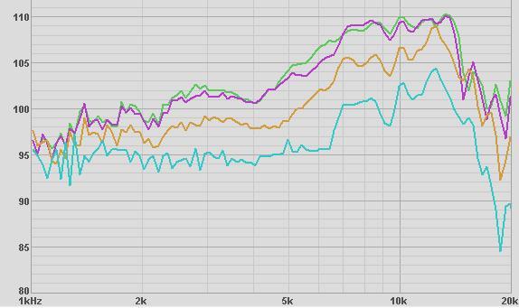
Now with the smaller caps, we get less MF contamination, but we also get not enough VHF boost, so let's try a larger cap:
1. No HF bypass (green)
2. 1.0 uF only (no L, no R) (blue)
3. 1.5 uF (aqua)
4. 1.5 uF in series with 0.05 mH (magenta)
5. 1.5 uF in series with 0.1 mH (yellow)
To my eye, curve 4 looks the best as 5 gives up some VHF, so it makes more sense to me to go with a 1.5uF cap in series with a 0.05 mH coil and then try to tame the resulting MF/HF bump with an LCR across the LE85. Using a blow up of the above curve, I determined the F3l = 6300; F3h = 15000 (although very steep here). (F3h-F3l)=8700 width, "midpoint" = F3l+((F3h-F3l)/2) = 10650, but visually the midpoint measures out nearer 8750. I think I will try an LCR based on that freq. (with about 10dB total from 4k to 18k.)
MarkT
To answer Zilch's questions about polar response, I took measurements @ 0, 10, 20, 30, 45 degrees off axis. (The actual degrees may be a bit off, I was using a plastic protractor held on the horn's mouth with a stick to the mike.) I am not sure about the absolute dB as I am sure the distance to the mike varied as I moved it off center, but at least the shape of the curves should be correct. (I do not know how to do a polar plot from these curves.)
Green = on axis
Magenta = 10 degrees off axis
Yellow = 30
Aqua = 45
MarkT
Looks to me like your best curves are without any HF boost. You may have to suck it up and either take what your getting or add a 2405. You can try what they did on the 4430 with a series LCR but it looks like you have a brick wall at 15K.
Rob
Your L & C tests confirm my findings. As you raise the C, the boost starts at a lower frequency. As you lower the L, it cuts off at a higher one.
My approach to it was to start the boost where it's needed, above 10 kHz, and stop it just above 20 kHz. Try the combination I found worked best, 0.5 uF and 0.05 mH. That gives ~9 dB of boost between 10 and 20 kH, the max you're going to get out of 6 dB/octave topology, plus ~3 dB from resonance.
You're already too high at 10 kHz. It doesn't make a lot of sense to me to boost that even higher and then yank it back down with a deeper notch.
*****
Your beamwidth tests indicate that the VHF is concentrated in a 20° "window," as discussed above. For most accurate results, the mic has to be at the same distance for each reading.
I use the "Move the mic" approach, too, with string used to hold the distance to mic constant. Another approach is a lazy susan under the speaker to rotate it about the acoustic center. I have a motorized rotary table for that, but haven't built it up yet.
To plot in true polar coordinate format requires a level of precision in positioning I have not achieved here. That's also multiple plots at different frequencies, a different way of looking at it....
OK, I have some interesting results. First the calculations:
Based upon a 10dB hump, I calculated R= 3.5
With F0=8750, F3h=15000, F3l=6300, I got L=0.05, C=5.37. I had a 0.06mH coil so used that with 5.5, 4.0, 3.0 uF caps.
First, here are the nulls (R=0) to show the center freq of the above combos:
green=no LCR (but WITH hipass = 1.5uF in series with 0.05mH, no R)
blue = 5.5uF
aqua = 4.0uF
yellow = 3.0uF
This pretty much confirms the F0 expected.
Then for each cap, I adjusted R for what looked like the best curve. Here are the results:
green=no LCR (but WITH hipass = 1.5uF in series with 0.05mH, no R)
aqua = 5.5uF, 2.1R
blue = 4uF, 2.5R
magenta = 3uF, 1.5R
To my eye, the magenta (3uF, 1.5R) looks the best, but it now has an 'M' - two humps and a notch which I think indicates I need a broader notch to pull down the humps on each side. That would require a smaller Q, but a smaller Q won't "pull down" the original hump enough. So now what?
Here are some 'families' of curves.
For 3.0uF, R varied 0, 1, 1.5, 2, 5
For 4.0uF, R varied 0,1,2,3
For 5.5uF, R varied 1,2,3 (I forgot to include the R=0, but you can see it above)
None of the curves seem to get broad enough to flatten things out. I'm not sure where to go next.
MarkT
Looks like Robh might be right. Here is a recap of boost with just a capLooks to me like your best curves are without any HF boost.
green=0
blue = 0.4uF
Aqua=0.5
Orange = 0.68
Yellow = 1.0
Magenta = 1.5
Per Zilch's suggestion, here are the results with 0.5uF cap
blue = no boost
green= just 0.5uF
magenta = 0.5uF with 0.05mH (Zilch's choice)
yellow = 0.5uF with 0.1mH
pumping in anything above 14k just raises 11-12k too much. I tried notching them out, but couldn't come up with anything worth posting as by the time I got the 10k notch tamed, I lost most of what I had gained above 15k.
I think at this point I amo going to work on getting the speakers finished and in the room and then maybe play with the XO more after listening to music.
(Now there's an idea!)
MarkT
You got within +/- 3 dB with a couple of those options.
That's damn good, I'd say....
Complete:
And mirror-imaged, to boot.
[Ooops, not the L-pads, tho....
Finally had time to do impedance plots on my LE85 driving both the tractrix and H91 horns. I discovered that my Freq. generator falls off in output at high freq. so this time I recalibrated for every single measurement! Numbers are much more as expected, but it does show far less swings for the tractrix. Later maybe I can repeat with the ||20R and/or the rest of the network. (Still not 100% sure of how to attach drive/measurement for that one.)
MarkT
- Thanks for taking the time to correct the impedance plot you get for your le85 driver .
- FWIW, many horns that have large aspect ratio mouths ( in comparison ) to the H91 , show a reduction of those impedance ripples ( or impedance reflections ). It's worth looking at Widgets' impedance plots of his H4003 (?) horn clones ( I think that plot is posted in the public forums ) .
- I've mentioned this a couple of times so;
- I'm going to have to leave this to someone else since I'll be "toast" till sometime Friday due to a strenuous work schedule .
A few OBSERVATIONS :
(i) Mark, you've really put your TrueAudio software through its' paces. More so ( to date ) than anyone who has posted their results from using that software .
- Congratulations on that !.
(ii) You've shown ( & are aware of ) many of the competing approaches that occur when one is searching for enhanced HF response .
- I've drawn different conclusions from what you've just recently stated. ( I'll expand on that comment later in the week ) . I guess in the meantime, as you say, it's time to get the speakers loaded and playing in your living room .
- FWIW ; I use a round mouthed exponential horn on a Altec 288-8K ( that supports 800 hz fairly well ). The horns rising Directivity Index ( DI factor ) means I need to use a series LCR ( strapped across the driver ) to flatten a quite symetrical peak ( centered around 6200 hz ) . I also use a pretty simple HF bypass circuit that does ( somewhat ) overdo the HF content ( and therefore, "contaminates" the octave below /as you have run into / & forces the need for a bigger notch )
regards;
There are currently 4 users browsing this thread. (0 members and 4 guests)
 Posting Permissions

 Reply With Quote
