Then you can try both and decide for yourself. Early versions used the 2421B and later versions used the 2425J. You may find the 2420 works just fine. The disagreements are based on opinion so form your own.Originally Posted by ayaboh


Then you can try both and decide for yourself. Early versions used the 2421B and later versions used the 2425J. You may find the 2420 works just fine. The disagreements are based on opinion so form your own.

I plan to use Giskards modified 3145 passive network as a starting point for this project, and also use a DSP or digital EQ for room/speaker correction. Is it possible to use only the frequency dividing components in the network, leave the L-Pads out of the circuit, and use the DSP for levelling of the drivers, or is this just BS? Is it better to build complete networks and then add the DSP? Has anyone here tried this, or something similar?

I don't think you can use the DSP to equalize the driver levels when using a passive crossover, since the levels are far apart.
But you can select a level of padding and do it with fixed resistors to within a couple of dB and let the DSP do the rest.
Johnny Haugen Sørgård
I don't know the range or limits of different DSPs or digital EQs, but it should be no problem to reduce the level of a driver up or down at least 12-15 db. I'm currently using a digital EQ on my sub and it has a range of up to +-24 db. You may be right about the rest, just use a complete network and EQ the whole thing.
Eq applied will affect not only the intended driver.
This works as intended if the driver levels are almost equal.
Johnny Haugen Sørgård
How do I calculate the neccessary power handling for the resistors in the network? In Giskards part list for the equivalent charge coupled network, its only used one or two 12W Mills in parallell. Is 12-24W enough for MF, HF and UHF?
Is this Giskards modified passive 3145 network?
And this the modified charge coupled network?
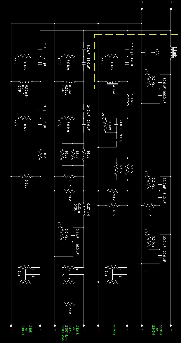
For me it is but for someone who plans on really stepping into them they should gang up on resistors. I'm finalizing the third edition hopefully in the next few weeks. There is currently more interest in the 4355 so that has taken precedent.
There are plenty of power calculators that are web based so rather than waste time posting the formulas you can just do a Google search on L-pad attenuation.
Thanks.
Just want to follow what has been done before. I can always play with other parts when everything works.
[QUOTE=ayaboh;135511]Ok, as promised, here are the production plans for the stock (or close to stock) 4344.
Thanks for this great thread and post!
You've framed up my fantasy. I don't plan to get K2 9800s or the new Everests any time soon, but building a pair of these "upgraded" 4344s is a real temptation.
I'm going to wait to see how the crossovers work out and if anyone makes these available on this forum, then the project would seem doable.
I love my 4343s, but I suspect these 4344s would make me even more content.
Thanks again for your contribution.
Tom
I am going to make one run of them for forum members. So far I have five pairs to do. I should have them finalized in a couple weeks. The 4355's have been far more popular and have taken up most of my time.
I have added MDF and veneer layout, and a preliminary part list to the pdf file http://designcut.com/4344org/4344.pdf. I have also added dxf files for the MDF layout http://designcut.com/4344org/Layout%2019mm%20MDF.dxf and http://designcut.com/4344org/Layout%2025mm%20MDF-1.dxf.
The dxf files can be used directly by a workshop with CNC cutting equipment (like high pressure water-jet systems), so it's no need to do full scale markings for the details on the MDF plates. The dxf files are enough.
The veneer layout is on a Lignaflex standard dimension sheet.
The drawings are now in rev 1.2, and I will send the MDF plates to the work shop for cutting within a couple of weeks. The grill frames are changed to all MDF to make it simpler to assemble, and the 2420s are changed to 2425s. Most of the detail drawings have been revised to make them easier to follow. The new drawings and DXF files can be downloaded here http://designcut.com/4344org/4344-1.2.pdf and here http://designcut.com/4344org/Material%20Layout.zip.
I have received grill cloth from Zilch, and I'm working on a system to attach the fabric to the frames with a rubber or plastic cord/spline instead of using an adhesive.
Now, - if I could talk Giskard into making me a couple of networks ......
Contact riessen
Here is the final version of the 4344 drawings http://designcut.com/4344org/4344-Final.pdf, dxf files for material layout http://designcut.com/4344org/Material%20Layout.zip, and ai files for the foilcals http://designcut.com/4344org/Foilcals.zip.
These are actually the as-built drawings for the project. Several things have been changed in this version, and some of the changes have been made during the building period. (I have removed the old files from the server).
A bracing between the back wall and the dog box has been added. This should make the cab a bit stiffer, and also support the center of the baffle.
4 mm asphalt plates are added to the least supported areas of the cabinet, and also to the back plate of the dog-box.
I had to skip the plan of using rubber or plastic splines to attach the fabric to the grill frames. I could not find anything I liked, so I ended up using hot-glue instead. This worked out fine.
A new back connector plate is used with cutouts for speaker terminals and a 9V battery box for charge coupled network.
I tried to attach the baffle foilcals to the baffle with six small super-magnets to make it easy to remove the foilcals and get access to the L-Pad Knobs and L-Pads. This was no success, and I'm now back to some sort of glue or tape.
I had to give up the hunt for original L-Pad knobs, and decided to make my own instead. This was actually very easy, and probably much cheaper than a set of originals. Drawings are included in the docs.
The network boxes have been removed from the drawings. They turned out to be way too small for all the caps and inductors when I finished the 3D modeling. These things are huge! See the drawings. I will make some layout drawings of the network boards later.
A list of nuts and bolt are the only things missing from the documentation, but it should be rather easy to figure out the right amount for all the bits and pieces. I guess US-based builders don't want to use metric screws anyway.
The only deviation from the drawings is that I have used the supplied T-Nuts and bolts that came with the 2123 drivers.
I will post some pics when the cabs start to look good (paint, veneer, and so on).
There are currently 8 users browsing this thread. (0 members and 8 guests)
 Posting Permissions

 Reply With Quote